A properly designed 24V solar system offers better efficiency, lower current, reduced voltage drop, and stronger inverter performance compared to standard 12V systems. For cabins, RVs, workshops, sheds, off-grid homes, and backup power systems, a 24V setup is often the most practical balance between affordability and performance.
In this guide, we explain the complete 24V solar system wiring diagram, including battery wiring, solar panel configuration, MPPT charge controller setup, inverter connections, fuse sizing, cable selection, and critical safety procedures.
Table of Contents
What Is a 24V Solar System?
A 24V solar system uses a 24-volt battery bank as the core energy storage source. Solar panels charge the batteries through an MPPT charge controller, and an inverter converts 24V DC power into usable AC electricity for household appliances.
The standard configuration includes:
- Solar panels
- MPPT solar charge controller
- 24V battery bank
- Pure sine wave inverter
- DC fuses and breakers
- Busbars
- Disconnect switches
- AC distribution panel
- Properly sized copper cables
The most common battery arrangement is: Two 12V Batteries in Series = 24V
This is the standard and safest method.
Example:
| Battery Setup | Voltage | Capacity |
|---|---|---|
| 1 × 12V 200Ah | 12V | 200Ah |
| 2 × 12V 200Ah in Series | 24V | 200Ah |
| 4 × 12V 200Ah in 2S2P | 24V | 400Ah |
Important rule: Series increases voltage. Capacity stays the same.
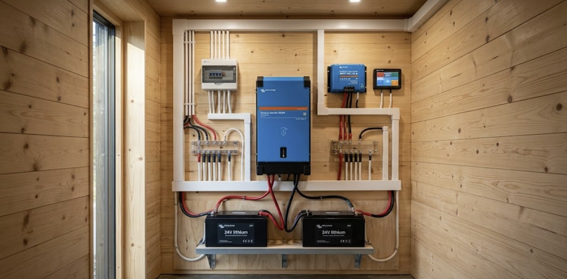
24V Solar System Wiring Diagram Overview
The basic wiring path follows this sequence:
- Solar panels generate DC power
- MPPT charge controller regulates charging
- Battery bank stores energy
- Inverter converts DC to AC
- AC breaker panel distributes power
Mermaid Wiring Diagram
When wiring your bank, consider adding a thermostat-controlled heater. We explain how to integrate this in our [winter solar charging lithium batteries] installation guide.
24V Solar System Wiring Diagram for Batteries
The battery bank is the heart of the system.
Standard Battery Wiring
For most installations:
- Use two identical 12V batteries
- Same brand
- Same capacity
- Same age
- Same chemistry
While wiring two 12V batteries in series works, every extra cable is a potential point of failure. If you haven’t bought your batteries yet, do yourself a favor and get a native [LiTime 24V 100Ah Battery]. By using a single 24V unit, you eliminate the need for a battery balancer and reduce your high-current connections by 50%. It results in a much cleaner, more reliable 24V wiring diagram that is significantly easier to troubleshoot.
Check current price on Amazon –>
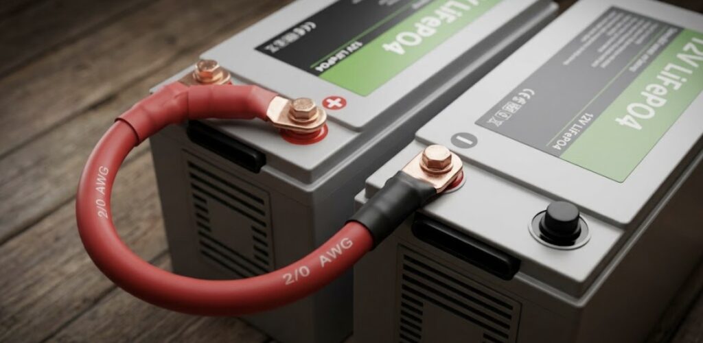
Series Wiring Method
Connection:
- Battery 1 positive → system positive
- Battery 1 negative → Battery 2 positive
- Battery 2 negative → system negative
This creates: 24V total voltage
while maintaining the same Ah rating.
Example
Two 12V 200Ah LiFePO4 batteries:
- Final output = 24V
- Capacity = 200Ah
- Total stored energy = 4,800Wh
Calculation:
24V × 200Ah = 4,800WhWhen wiring batteries in series, ensuring they are perfectly balanced is critical. Check our engineering picks for the [best solar battery for cabin] to find units with advanced BMS for series configurations.
Solar Panel Wiring for a 24V System
Solar panels must provide voltage higher than battery voltage.
Minimum Requirement
For a 24V battery bank: Minimum 2 panels in SERIES
This ensures charging voltage exceeds battery voltage.
Why Series Matters
A single “12V” solar panel usually produces:
- Vmp ≈ 18V
- Voc ≈ 22V
This is not enough for a 24V battery system.
Two panels in series produce:
- Vmp ≈ 36V
- Voc ≈ 44V
This is ideal for MPPT charging.
Example Configuration
| Panel Setup | Result |
|---|---|
| 1 × 12V panel | Not enough |
| 2 × 12V panels in series | Correct |
| 4 panels (2S2P) | Higher power |
Series Connection
- Panel 1 negative → Panel 2 positive
Remaining ends go to controller:
- Final positive → Controller PV+
- Final negative → Controller PV−
Your choice of panels determines your total voltage overhead. See the [best solar panels for tiny house] for 2026 to pick the most efficient modules for your array.

MPPT Charge Controller Selection
An MPPT controller is mandatory for 24V efficiency.
PWM controllers waste voltage and reduce charging performance.
Why MPPT Is Required
MPPT:
- Converts excess panel voltage into charging current
- Improves winter charging
- Increases harvest by 20–30%
- Supports higher-voltage panel strings
Sizing your controller is only half the battle; choosing the right brand matters for long-term harvest. Compare the top options in our [Victron vs Renogy charge controllers] guide.
Controller Sizing Formula
Use:
Total Solar Watts ÷ Battery Voltage = Controller Current
Then add 25% safety margin.
Example
600W solar array:
600 ÷ 24 = 25A
25 × 1.25 = 31.25A
Recommended controller: 40A MPPT
Common Sizes
| Solar Array | Recommended MPPT |
|---|---|
| 400W–600W | 40A |
| 800W–1200W | 60A |
| 1500W+ | 80A+ |
Inverter Wiring for a 3000W 24V System
A 3000W inverter is the most common size for serious off-grid use.
It can power:
- Refrigerators
- Microwaves
- Power tools
- Pumps
- Coffee machines
- Small air conditioners
- Workshop equipment
A 3000W inverter is a high-performance component. See how the industry leaders stack up in our [Renogy vs Victron] ultimate comparison. Or also our more specific [Renogy vs Victron inverter comparison].
Required Cable Size
For a: 3000W 24V inverter
Use: Minimum 2/0 AWG pure copper cable
This reduces:
- Voltage drop
- Heat buildup
- Fire risk
Quality Warning: Don’t fall for cheap “CCA” (Copper Clad Aluminum) cables. Aluminum has higher resistance and can overheat under the 125A+ loads of a 3000W inverter. I only use [WindyNation 100% Pure Copper 2/0 AWG]. This “welding grade” cable is extremely flexible—making it easy to route through tight cabin corners—and ensures your inverter gets the full voltage it needs without dangerous heat buildup.
Check current price on Amazon –>
Current Calculation
3000W ÷ 24V = 125A+
Startup surge may be much higher.
This is why thick copper cable is required.
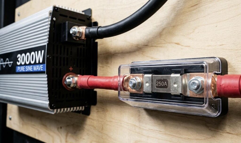
Recommended Fuse Size
Battery-to-inverter fuse: 250A fuse
This is the safe standard for most 3000W 24V systems.
Preferred fuse type:
- For a 24V Lithium system, a standard “car audio” ANL fuse is not enough. Lithium batteries can dump thousands of amps in a microsecond during a short circuit, which can literally weld an inferior fuse shut. I always specify a [Blue Sea Systems Class T Fuse]. It is the only fuse type with an extremely high interrupt rating specifically designed to stop a lithium “thermal runaway” event. It’s a $60 investment that protects a $5,000 system. Check current price on Amazon –>
Class T fuses are required for lithium systems due to their high interrupt rating. Refer to the [Blue Sea Systems Circuit Protection Guide] for technical specs.
Correct Connection Order (Critical Safety Rule)
This prevents controller damage.
Always Follow This Sequence
| Step 1: | Connect: Battery → Charge Controller FIRST |
| Step 2: | Connect: Battery → Inverter |
| Step 3: | Connect: Inverter → AC Loads |
| Step 4. | Connect: Solar Panels → Charge Controller LAST |
Never reverse this order.
Controllers must initialize from battery voltage first.
Failure to do this may damage the MPPT controller.
Fuse and Breaker Placement
Protection devices are not optional.
They prevent:
- Short circuits
- Fire
- Cable overheating
- Equipment failure
24V Solar System Wiring Diagram for Fuses
Required Protection Points
| Location | Recommended Protection |
|---|---|
| Panels → MPPT | DC breaker |
| MPPT → Battery | DC fuse |
| Battery → Inverter | 250A fuse |
| Inverter → AC loads | AC breaker panel |
Additional Safety
Recommended:
- Battery disconnect switch
- Surge protection
- Busbars
- Grounding system
Cable Size Reference Table
Correct wire size prevents dangerous voltage drop.
| Connection | Typical Cable |
|---|---|
| Panels to MPPT | 10 AWG |
| MPPT to Battery | 6–4 AWG |
| Battery to Inverter | 2/0 AWG |
| Grounding Cable | According to code |
Using the wrong gauge is the #1 cause of system failure. For a deeper look at the physics of wire size and voltage, review our [12V vs 24V vs 48V solar system] engineering comparison.
Always use: Pure copper stranded cable
Avoid undersized aluminum wire for battery cables.
The sizes in this table are estimates for short runs. For long distances or custom setups, use our [solar panel wire size] guide to calculate the exact gauge needed for your voltage drop.
24V Solar System Example for Off-Grid Shed
System Components
- 2 × 12V 200Ah LiFePO4 batteries
- 2 × 300W solar panels
- 40A MPPT controller
- 3000W pure sine wave inverter
- 250A fuse
- 2/0 AWG inverter cable
- DC breakers
- Battery monitor
Before building this shed setup, make sure you’ve audited your energy use. Use the formulas in our [400 sq ft cabin power consumption] guide to be certain.
Daily Loads
| Appliance | Usage |
|---|---|
| LED lights | 300Wh |
| Power tools | 3000Wh |
| Fan | 300Wh |
| Laptop | 400Wh |
| Total | 4000Wh |
Battery storage:
24V × 200Ah = 4800Wh
This is a strong practical setup for a workshop, RV, or backup system.
Common Mistakes to Avoid
Connecting Batteries of Different Age
Never mix:
- old and new batteries
- different brands
- different capacities
This causes charging imbalance.
Using PWM Instead of MPPT
A 24V system should use MPPT for proper efficiency.
PWM wastes panel potential.
Undersized Inverter Cables
Thin cable causes:
- voltage drop
- overheating
- inverter shutdown
Use 2/0 AWG for 3000W systems.
No Battery Fuse
This is one of the most dangerous mistakes.
Always install a 250A fuse near the battery.
Connecting Panels First
Never do this.
Battery must be connected to controller first.
Best Practices for Long-Term Reliability
We recommend:
- lithium batteries for deeper discharge
- pure sine wave inverter only
- MPPT charge controller only
- copper cable only
- regular terminal inspection
- proper torque on battery terminals
- battery monitor with shunt
- Bluetooth monitoring where available
These upgrades improve efficiency and system lifespan significantly.
Final 24V Solar System Wiring Checklist
Before startup, verify:
- Battery polarity correct
- Series battery wiring correct
- Solar panel voltage verified
- MPPT controller sized properly
- 250A inverter fuse installed
- 2/0 AWG inverter cable installed
- Breakers installed
- Grounding complete
- Battery connected first
- Panels connected last
This checklist prevents most installation failures.
Conclusion
A correct 24V solar system wiring diagram is the foundation of a safe and efficient off-grid power system. Two 12V batteries in series create the battery bank, at least two solar panels in series provide charging voltage, an MPPT controller manages charging efficiency, and a properly fused 3000W inverter delivers reliable AC power.
The most important rules remain simple:
- Use MPPT only
- Use 2/0 AWG for 3000W inverter wiring
- Install a 250A battery fuse
- Connect battery to controller first
- Connect panels last
Wiring is the final step in a larger journey. Integrate this diagram into your [complete off-grid power blueprint for retreat cabins] for a professional, resilient installation.
Following these standards creates a reliable, professional-grade 24V solar system built for long-term performance.
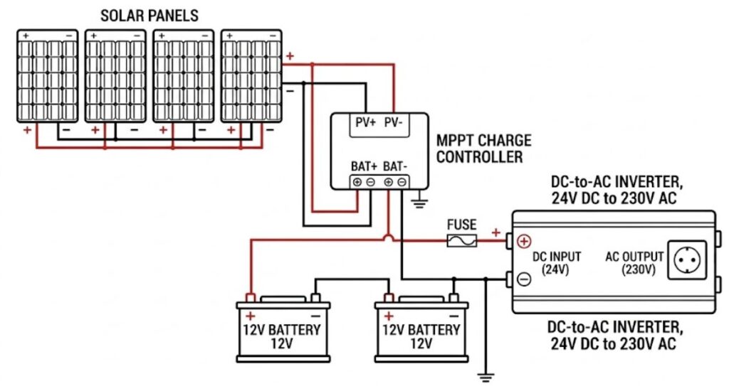
What is the basic 24V solar system wiring diagram?
A basic 24V solar system wiring diagram includes solar panels, an MPPT charge controller, a 24V battery bank made from two 12V batteries connected in series, a pure sine wave inverter, safety fuses, DC breakers, and AC loads. The solar panels generate DC electricity and send it to the MPPT charge controller, which regulates the charging process and safely charges the 24V battery bank. The inverter then converts the stored 24V DC power into AC power for running appliances such as lights, refrigerators, tools, and pumps. In most installations, at least two solar panels are connected in series so the voltage is high enough to properly charge the batteries. A correct 24V solar system wiring diagram always follows the safe connection order where the battery is connected to the charge controller first, then the inverter is connected to the battery bank, then the AC loads are connected, and finally the solar panels are connected to the controller. This sequence protects the MPPT controller and ensures safe startup of the entire system.
How do two 12V batteries work in a 24V solar system wiring diagram?
In a 24V solar system wiring diagram, two 12V batteries are connected in series to create a 24V battery bank, which is the most common and reliable setup for off-grid solar systems. This is done by connecting the negative terminal of the first battery to the positive terminal of the second battery, while the remaining free positive and negative terminals become the main system output for the charge controller and inverter. This series connection increases the system voltage to 24V while keeping the amp-hour capacity the same, which means two 12V 200Ah batteries become 24V 200Ah, not 24V 400Ah. This is a key principle in every 24V solar system wiring diagram because many installers incorrectly assume capacity also doubles. For best performance, both batteries should be identical in voltage, capacity, age, and chemistry to prevent charging imbalance, shortened battery life, and system inefficiency.
Why is MPPT required in a 24V solar system wiring diagram?
An MPPT charge controller is required in a proper 24V solar system wiring diagram because it provides higher charging efficiency, better battery protection, and improved solar energy harvesting compared to a PWM controller. MPPT stands for Maximum Power Point Tracking, and it works by converting extra solar panel voltage into additional charging current, which is especially important in a 24V system where solar panels are usually wired in series for higher voltage. A PWM controller simply cuts down the voltage and wastes valuable power, while MPPT allows the system to use that extra voltage efficiently. This results in faster charging, better winter performance, stronger low-light charging, and improved overall system output. Since solar panels in a 24V solar system wiring diagram often produce much higher voltage than the battery bank requires, MPPT is considered mandatory rather than optional.
How many solar panels are needed in a 24V solar system wiring diagram?
A 24V solar system wiring diagram requires at least two solar panels connected in series because a single standard 12V solar panel does not produce enough voltage to charge a 24V battery bank effectively. Most 12V solar panels produce around 18V operating voltage and about 22V open circuit voltage, which is too low for a 24V battery system. When two panels are wired in series, the voltage increases to around 36V operating voltage and more than 40V open circuit voltage, which is ideal for MPPT charging. Larger systems may use four, six, or more panels depending on the daily energy demand and battery storage capacity. The exact number depends on the wattage requirements of the appliances being powered, available sunlight hours, and backup power goals, but the minimum starting point in every 24V solar system wiring diagram is always two panels in series.
What cable size is needed for a 3000W inverter in a 24V solar system wiring diagram?
In a 24V solar system wiring diagram using a 3000W inverter, the recommended minimum cable size between the battery bank and the inverter is 2/0 AWG pure copper cable because the inverter can draw more than 125 amps under full load. This high current requires thick cable to prevent voltage drop, overheating, poor inverter performance, and serious fire risk. The current calculation is simple: 3000 watts divided by 24 volts equals more than 125 amps, and startup surge loads can be significantly higher depending on the appliances connected. Thin or undersized cables can cause the inverter to shut down unexpectedly, reduce system efficiency, and damage sensitive electronics. For this reason, professional installers always use heavy pure copper cable instead of cheaper aluminum alternatives in a serious 24V solar system wiring diagram.
What fuse size should be used in a 24V solar system wiring diagram?
For a 3000W inverter setup, the standard fuse size used in a safe 24V solar system wiring diagram is a 250A battery fuse installed between the battery bank and the inverter. This fuse protects the cables, batteries, inverter, and the entire DC side of the system from dangerous short circuits and overload conditions. The fuse should be installed as close to the battery as possible so that if a fault occurs, the system can disconnect power immediately before cables overheat or catch fire. Common fuse types include Class T fuses for maximum protection and ANL fuses for more budget-friendly installations. A proper 24V solar system wiring diagram should never operate without a correctly sized battery fuse because this is one of the most important safety components in the entire system.
What is the correct connection order in a 24V solar system wiring diagram?
The correct connection order in a 24V solar system wiring diagram is extremely important for safety and equipment protection. The battery bank must always be connected to the MPPT charge controller first so the controller can detect system voltage and initialize properly. After that, the inverter is connected to the battery bank, followed by the AC loads, and the solar panels are connected last. Connecting the solar panels first can damage the controller and cause charging problems, so this rule should never be ignored.
6 thoughts on “24V Solar System Wiring Diagram: Complete Guide for Safe and Efficient Installation”