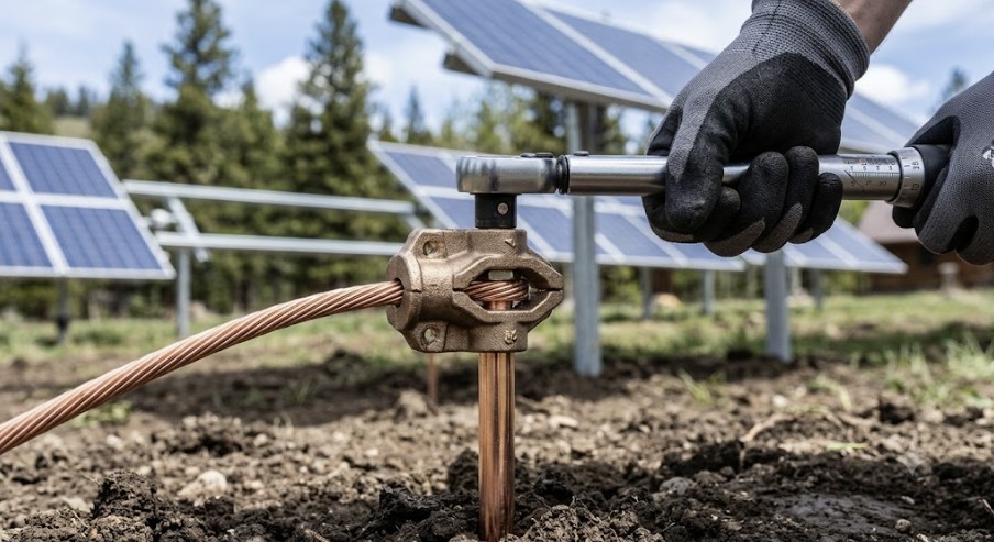
Properly grounding a solar panel system is the single most critical safety measure you can implement. It is not optional, nor is it a corner you can afford to cut. An effective grounding system protects your expensive equipment from electrical surges and, more importantly, protects you and your family from potentially lethal electrical shock.
This definitive guide provides the engineering principles, National Electrical Code (NEC) requirements, and product analysis needed to select and install the best ground rod for solar panels, ensuring a safe and reliable off-grid or grid-tied power system for years to come.
Table of Contents
The Core of Electrical Safety: Understanding the Grounding Electrode System
Before selecting hardware, it’s crucial to understand the components of a solar grounding system. Many people confuse the different grounding conductors, but they serve distinct purposes. The ground rod is the centerpiece of the Grounding Electrode System (GES).
The GES is your system’s physical connection to the earth. It provides a safe path for fault currents, lightning-induced surges, and static electricity to dissipate harmlessly into the ground. A properly installed, low-resistance connection to earth is the foundation of electrical safety.
Grounding Electrode Conductor (GEC) vs. Equipment Grounding Conductor (EGC)
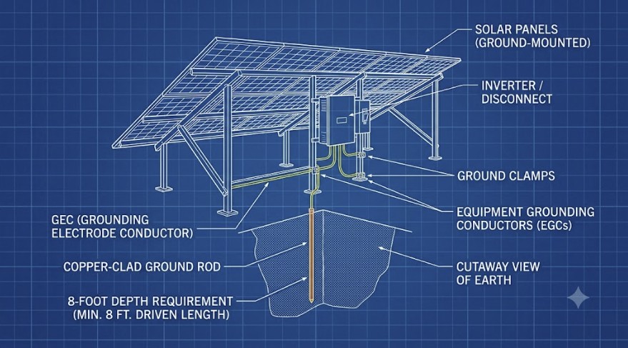
Your solar installation uses two primary types of grounding wires. The GEC is the large copper wire that runs from your main disconnect or inverter to your ground rod. The EGC is the wire that bonds all metallic, non-current-carrying components (panel frames, racking, inverter chassis) together, creating a continuous safety path.
Understanding this distinction is key. The EGC ensures that if a wire faults and energizes a panel frame, the current has an immediate path back to the source to trip a breaker. The GEC and ground rod ensure the entire system is referenced to earth potential. Choosing the best ground rod for solar panels directly impacts the effectiveness of your GEC.
| Feature | Grounding Electrode Conductor (GEC) | Equipment Grounding Conductor (EGC) |
|---|---|---|
| Purpose | Connects the system’s service equipment to the earth via a grounding electrode (ground rod). | Bonds all metal enclosures and racking to provide a path for fault current to the source. |
| Connection Point | From the main AC/DC disconnect to the ground rod(s). | Interconnects all panel frames, mounting rails, inverter chassis, and combiner boxes. |
| Typical Conductor | Solid or stranded bare copper (or green insulated). Typically #6 AWG or larger. | Bare copper or green insulated wire. Size is based on the overcurrent protection device. |
| NEC Reference | NEC Article 250, Part III & NEC Table 250.66 | NEC Article 690, Part V & NEC Table 250.122 |
Decoding NEC Requirements for the Best Ground Rod for Solar Panels
The National Electrical Code (NEC) provides strict, non-negotiable rules for grounding electrodes to ensure safety. Complying with NEC Article 250 is mandatory for any permitted solar installation. The key is to establish a low-impedance path to earth, which means the electricity should face as little resistance as possible when flowing to the ground.
According to NEC 250.52(A)(5), a rod-type electrode must meet specific physical criteria. These standards are the absolute minimum for any product you consider.
- Minimum Length: The ground rod must be at least 8 feet (2.44 m) in length.
- Material and Diameter: It must be at least 5/8 inch (15.87 mm) in diameter if it is a steel rod. For non-ferrous rods like solid copper or stainless steel, the minimum diameter is 1/2 inch (12.7 mm).
- Direct Earth Contact: At least 8 feet of the rod’s length must be in direct contact with the surrounding soil. This is why you must drive it fully into the ground.
- Installation Depth: The rod must be driven vertically until its top is at or below the ground level. If you hit rock, you can drive it at an angle not exceeding 45 degrees from vertical, or as a last resort, bury it in a trench at least 30 inches deep.
- Multiple Rods: If a single rod does not achieve a resistance to ground of 25 ohms or less (verified by a ground resistance tester), a second rod is required. The supplemental rod must be installed at least 6 feet away from the first one.
Failure to meet these requirements can result in a failed inspection and an unsafe system. When choosing the best ground rod for solar panels, always verify that it is UL Listed and meets these NEC dimensional standards.
Material and Type Analysis: Choosing the Best Ground Rod for Solar Panels
While the NEC sets the minimum standards, the material of your ground rod significantly impacts its longevity and performance, especially in different soil conditions. The best ground rod for solar panels is one that provides a durable, low-resistance path to earth for the life of your system.
Copper-clad steel is the most common and cost-effective choice for most residential and off-grid applications. It offers a good balance of conductivity, strength, and corrosion resistance.
| Material Type | Pros | Cons | Best Use Case |
|---|---|---|---|
| Copper-Clad Steel | Excellent conductivity, high strength for driving, affordable, good corrosion resistance. | Copper cladding can be damaged if driven improperly, exposing steel to rust. | The vast majority of residential, commercial, and off-grid solar systems. |
| Galvanized Steel | Very strong, very affordable. | Lowest conductivity, zinc coating offers limited corrosion protection, shorter lifespan. | Temporary installations or budget-critical projects where local code allows. |
| Solid Copper | Highest conductivity, superior corrosion resistance (will not rust). | Expensive, softer material can bend or mushroom when driven into rocky soil. | Highly corrosive (saline or acidic) soil environments where longevity is paramount. |
| Stainless Steel | Extremely high strength, excellent corrosion resistance. | Lower conductivity than copper, very expensive. | Extremely rocky soil or highly corrosive industrial environments. |
Alternative Grounding Electrodes
While ground rods are most common, the NEC recognizes other electrode types that may be suitable or even superior depending on the construction of your off-grid cabin or home.
- Concrete-Encased Electrode (Ufer Ground): This involves using at least 20 feet of 1/2-inch rebar or 20 feet of #4 AWG bare copper wire embedded within the concrete foundation. Ufer grounds provide a massive surface area in contact with the earth and often yield the lowest ground resistance.
- Ground Plate: A metal plate with at least 2 square feet of surface area buried at least 30 inches deep. These are useful in very shallow or rocky soil where driving an 8-foot rod is impossible.
- Ground Ring: A ring of at least 20 feet of #2 AWG bare copper wire buried at least 30 inches deep encircling the structure. This is an excellent but expensive option for achieving very low ground resistance.
Top Rated: The Best Ground Rod for Solar Panels and Accessories
For most installations, the choice is straightforward. A high-quality, UL-listed, copper-clad steel rod is the industry standard for a reason. Here are our top engineering-approved picks.
1. ERICO 5/8 in. x 8 ft. Copper-Clad Pointed Ground Rod
This is the workhorse of the electrical industry and the quintessential best ground rod for solar panels. ERICO is a reputable brand, and this rod meets all NEC and UL requirements. The 10-mil copper cladding provides excellent conductivity and durability for a long service life.
The pointed tip makes it easier to drive into dense soil, and its rigid steel core prevents bending during installation. It offers the perfect combination of performance, compliance, and value for any standard solar project.
- Pros: UL Listed, meets NEC 250.52 requirements, industry-standard 10-mil copper bonding, durable steel core, excellent value.
- Cons: Can be challenging to drive manually without the right tools.
[Check Price for ERICO 5/8 in. x 8 ft. Copper-Clad Ground Rod on Amazon]
Check current price on Amazon –>
2. Burndy C-Clamp Direct Burial Ground Connector
The best ground rod for solar panels is useless without a reliable connection. A cheap, poorly made clamp is a critical point of failure. The Burndy C-Clamp is specifically designed for direct burial and made from high-copper alloy bronze, which resists corrosion and ensures a solid, permanent bond between the GEC and the rod.
This clamp’s robust design provides high contact pressure, essential for maintaining a low-resistance electrical connection over decades of exposure to moisture and temperature changes. Do not compromise on this component; it is just as important as the rod itself.
- Pros: UL Listed for direct burial, high-copper alloy construction for maximum durability, provides a secure and permanent connection, resists galvanic corrosion when used with copper wire.
- Cons: Higher initial cost than basic acorn clamps, but worth the investment.
[Check Price for Burndy C-Clamp Direct Burial Ground Connector on Amazon]
Check current price on Amazon –>
Proper Installation Technique for Your Solar Grounding System
Owning the best ground rod for solar panels means nothing if it is installed incorrectly. The goal is to achieve maximum surface area contact with undisturbed earth. This ensures the lowest possible impedance path.
First, use a utility locating service (“Call 811” in the US) to ensure you won’t hit buried pipes or cables. For installation, a manual post driver can work in soft soil, but for most situations, a rotary hammer drill with a ground rod driver bit is the most effective tool. It will drive the rod without mushrooming the top.
Drive the rod vertically until the top is flush with or just below the soil surface. After driving the rod, use a wire brush to clean the top of the rod and the GEC before attaching the clamp. Tighten the clamp to the manufacturer’s specified torque using a torque wrench. This ensures a gas-tight seal that prevents moisture intrusion and future corrosion.
The 25-Ohm Rule and Soil Resistivity
The NEC requires your grounding electrode system to have a resistance to earth of 25 ohms or less. In areas with sandy, rocky, or very dry soil, achieving this with a single rod can be difficult. Soil resistivity is the key factor.
An electrician or engineer can test this with a dedicated ground resistance meter. If the resistance is over 25 ohms, the code mandates that you install a second ground rod. The second rod must be spaced at least 6 feet from the first and bonded to it with a continuous GEC. This spacing is critical to ensure the rods are in different “spheres of influence” in the soil, effectively lowering the overall system resistance.
| Soil Type | Typical Resistivity (Ohm-meters) | Implication for Grounding |
|---|---|---|
| Moist Loam / Clay | 5 – 50 | Excellent. Often achieves <25 ohms with a single rod. |
| Dry Clay or Gravel | 100 – 500 | Fair to Poor. Likely will require two or more ground rods. |
| Sand or Sandy Loam | 500 – 2,000 | Poor. Will almost certainly require multiple rods or alternative electrodes. |
| Solid Rock | > 5,000 | Extremely Poor. Requires specialized grounding like ground plates, rings, or Ufer. |
Sizing Your Grounding Electrode Conductor (GEC)
The wire connecting your equipment to the best ground rod for solar panels must be sized correctly to handle potential fault currents. The NEC provides clear guidance in Table 250.66. The size of the GEC is based on the size of your largest ungrounded service-entrance conductor, which in an off-grid system is typically the main wire from your inverter to your electrical panel.
For most residential and cabin solar systems, a #6 AWG copper conductor is the minimum required for a connection to a rod electrode. However, you must always verify sizing against the code. A conductor smaller than #6 AWG must be protected from physical damage by being installed in conduit.
When planning your system, a comprehensive solar panel to battery sizing guide will help determine your main conductor sizes, which in turn dictates your required GEC size. Proper sizing is another non-negotiable aspect of a safe installation.
The Final Word on the Best Ground Rod for Solar Panels
Selecting the best ground rod for solar panels is not about finding an exotic or expensive product. It is about strictly adhering to engineering best practices and the National Electrical Code. For over 95% of solar installations in the United States, the ideal choice is a UL-listed, 5/8-inch by 8-foot copper-clad steel ground rod.
Combine this with a high-quality, direct-burial rated bronze clamp and a correctly sized GEC. This setup provides a safe, durable, and code-compliant Grounding Electrode System that will protect your investment and your life. Always consult the latest NEC version and your local authority having jurisdiction (AHJ) to ensure full compliance.
What is the minimum diameter for a solar panel ground rod?
According to NEC 250.52(A)(5), the minimum diameter depends on the material. For the most common steel or iron rods (including copper-clad steel and galvanized steel), the minimum diameter is 5/8 inch (15.87 mm). For rods made of non-ferrous materials like solid copper or stainless steel, the minimum diameter is a smaller 1/2 inch (12.7 mm).
Using a rod smaller than these dimensions is a code violation and will fail inspection. The 5/8-inch copper-clad steel rod is the industry standard and considered the best ground rod for solar panels in most applications due to its blend of strength, conductivity, and cost-effectiveness.
Do I need one or two ground rods for my solar system?
The NEC (250.53(A)(2)) states that a single ground rod is sufficient only if its resistance to ground is 25 ohms or less. This must be verified with a specialized ground resistance tester, an instrument most DIYers do not own. Because of this testing requirement, the vast majority of jurisdictions and best practices dictate installing two ground rods as a standard procedure.
By installing two rods spaced at least 6 feet apart, you comply with the code without needing to perform a resistance test. Therefore, for almost all installations, planning for two ground rods is the safest and most efficient approach to ensure compliance.
Can I use rebar as a ground rod for my solar panels?
No, you absolutely cannot drive a piece of rebar into the ground and use it as a ground rod. Rebar is not listed or tested for this purpose, its surface is often inconsistent and may have non-conductive coatings, and it does not meet NEC requirements for a manufactured electrode. Using rebar in this way is a serious safety hazard and a code violation.
However, rebar is the primary component of a Concrete-Encased Electrode (CEE), also known as a “Ufer ground.” This involves using at least 20 feet of #4 (1/2-inch) or larger rebar embedded in the concrete foundation of a structure, which is then bonded to the system’s GEC. A Ufer ground is an excellent, NEC-approved electrode, but it is not the same as using a standalone piece of rebar.
How does the best ground rod for solar panels differ from a lightning rod?
A ground rod and a lightning rod serve entirely different purposes. A ground rod for a solar system is part of the electrical safety grounding system. Its job is to provide a reference to earth potential and a path for electrical fault currents, tying directly into your electrical panels and equipment.
A lightning rod, part of a dedicated Lightning Protection System (LPS) under NFPA 780, is designed to intercept a direct lightning strike and channel its immense energy to earth through dedicated, heavy-gauge down-conductors and a separate grounding electrode system. The LPS should never be directly connected to your solar panel frames or electrical system wiring above ground; they are only bonded together at the grounding electrodes themselves.
What happens if I don’t ground my solar panel system?
Failing to ground a solar panel system creates an extremely dangerous situation. Without a proper ground, there is no safe path for fault currents to flow. If a wire becomes frayed and touches a panel frame or racking, the entire metal structure can become energized at potentially lethal voltages. Anyone touching it could receive a severe electrical shock.
Additionally, an ungrounded system has no protection against static electricity buildup or surges from nearby lightning strikes, which can easily destroy sensitive electronics like inverters and charge controllers. It is a major fire hazard and a life-safety risk.
How deep must the best ground rod for solar panels be buried?
The NEC requires a standard ground rod to be a minimum of 8 feet in length. The code (NEC 250.53(G)) also requires that this 8-foot rod be driven so that it is in direct contact with the soil for its entire length. This effectively means you must drive the entire rod into the ground until its top is at or below the final grade (ground level).
If you encounter rock and cannot drive it the full 8 feet vertically, you are permitted to drive it at an angle, not to exceed 45 degrees from vertical. If that is still not possible, the final option is to bury the 8-foot rod horizontally in a trench that is at least 30 inches (2.5 feet) deep.
What size copper wire should connect to my ground rod?
The copper wire that connects your main disconnect to the ground rod is the Grounding Electrode Conductor (GEC). Its size is determined by NEC Table 250.66, which is based on the size of your largest power-carrying service conductors. For most residential solar installations, the GEC is typically #6 AWG copper.
However, the absolute minimum size allowed for a GEC connecting to a rod electrode is #8 AWG copper, though this is uncommon. It’s critical to note that if the GEC is smaller than #6 AWG, it must be protected from physical damage by being enclosed in conduit like RMC, IMC, or Schedule 80 PVC.
Can I install a ground rod horizontally?
Yes, but only as a last resort. The NEC prioritizes vertical installation to reach deeper, more stable moisture levels in the soil, which provides lower resistance. A vertical rod is always the preferred method for the best ground rod for solar panels installation.
However, if you hit solid rock or other obstruction that prevents driving the rod vertically or at a 45-degree angle, NEC 250.53(G) permits you to bury the rod horizontally. The entire 8-foot rod must be placed in a trench that is a minimum of 30 inches deep to ensure it is below the frost line and in permanently moist soil.
What is a Ufer ground and is it a good choice for solar?
A Ufer ground, technically a Concrete-Encased Electrode (CEE), is a grounding system that utilizes the steel rebar within a building’s concrete foundation. It requires at least 20 feet of electrically conductive rebar (at least 1/2-inch diameter) to be bonded together and connected to the Grounding Electrode Conductor.
A Ufer ground is not just a good choice; it’s often the best possible grounding electrode. The large amount of rebar encased in concrete provides a massive surface area in contact with the earth, resulting in a very stable, low-resistance ground connection that is superior to driven rods in almost all soil conditions. If you are building a new cabin or structure for your solar equipment, incorporating a Ufer ground is a highly recommended practice.
How do I test the resistance of my ground rod installation?
Testing the resistance to earth of a ground rod requires a specialized piece of equipment called a ground resistance tester (often a 3-point or 4-point fall-of-potential tester). This is not a standard multimeter. The test involves driving dos additional temporary probes into the earth at specific distances from the ground rod under test.
The meter then injects a known current through the system and measures the voltage to calculate the resistance in ohms. Due to the cost of the equipment and the specific procedure required, this test is typically performed by licensed electricians or engineers. For DIY installers, the simplest way to comply with the NEC is to install dos rods spaced at least 6 feet apart, which negates the need for the test.
Does the material of the best ground rod for solar panels matter in different soil types?
Yes, absolutely. In normal, loamy, or clay soils with neutral pH, a standard copper-clad steel rod provides an excellent balance of performance and longevity. However, in highly corrosive soils, the choice of material is critical for the system’s lifespan.
For soils with high salinity (coastal areas), high acidity (peat bogs), or industrial contamination, the thin copper cladding can be compromised over time. In these harsh conditions, a solid copper or stainless steel ground rod, while more expensive, is a far superior choice. These materials are inherently resistant to corrosion and will maintain their integrity and low-resistance path to ground for much longer.
Why is the 6-foot spacing rule for multiple ground rods important?
The 6-foot minimum spacing is a critical NEC requirement based on electrical theory. Each ground rod dissipates current into the earth in a roughly hemispherical pattern, often called its “sphere of influence.” If a second rod is placed too close to the first (inside its sphere of influence), the dos rods will act as if they are one larger electrode, and the reduction in overall ground resistance will be minimal.
By spacing them at least 6 feet apart—and ideally further, like 10-16 feet if space allows—you ensure that their spheres of influence do not significantly overlap. This allows them to function as dos separate, parallel paths to earth, which more effectively lowers the total system resistance to ground, providing a safer path for fault current.