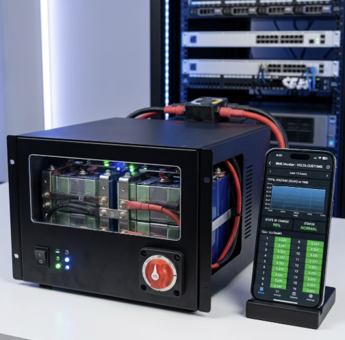
Building a custom LiFePO4 battery is a high-stakes engineering endeavor. The difference between a reliable, decade-long power source and a catastrophic failure lies in one critical component: the Battery Management System (BMS). A standard BMS offers basic protection, but for the precision, safety, and longevity required in off-grid solar systems, selecting the best smart BMS for custom LiFePO4 battery builds is paramount.
This guide moves beyond surface-level reviews, providing the essential engineering criteria, hardware analysis, and configuration parameters needed to protect your investment and ensure maximum performance. We will dissect the technical specifications that define a superior smart BMS, compare top-tier models, and outline the correct integration procedures for a safe and efficient DIY battery bank.
Table of Contents
Core Functions: Why the Best Smart BMS for Custom LiFePO4 Battery Builds is Non-Negotiable
A smart BMS acts as the brain of your battery pack, constantly monitoring and managing every cell group to maintain a safe operating envelope. Its functions are not optional features; they are fundamental to the chemistry of Lithium Iron Phosphate. Neglecting this component is a direct path to premature cell degradation and significant safety risks.
The primary role of the best smart BMS for custom LiFePO4 battery builds is to prevent conditions that damage the cells. This includes precise voltage, current, and temperature monitoring to trigger protective disconnects when parameters are exceeded. Without this vigilant oversight, your battery is vulnerable to irreversible damage.
Voltage and Current Protection
LiFePO4 cells have strict voltage limits. Overcharging, even slightly, can cause permanent capacity loss and, in extreme cases, thermal runaway. Similarly, over-discharging below the minimum voltage threshold can damage the cell’s internal structure. The BMS enforces these limits by disconnecting the charge or discharge path.
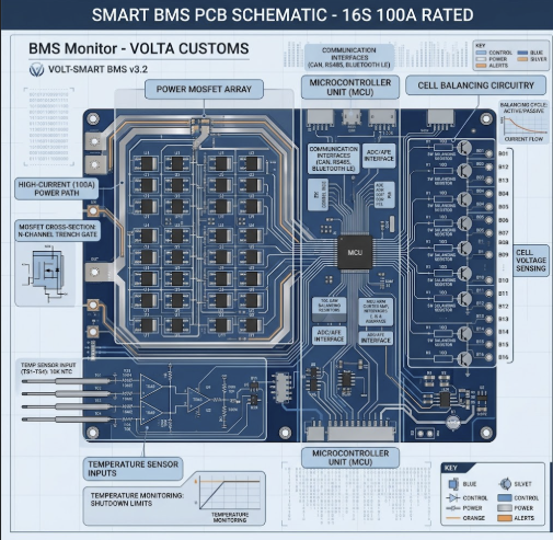
Overcurrent protection is equally vital. The BMS protects against both excessive discharge currents, which can overheat cells and wiring, and short circuits, which can lead to catastrophic failure. A robust BMS utilizes high-performance MOSFETs to instantly interrupt the circuit when a fault is detected, a feature essential for systems with large inverters that have high inrush currents.
Thermal Management
Temperature is a critical factor in LiFePO4 performance and safety. Charging below freezing (0°C or 32°F) can cause lithium plating on the anode, a dangerous and irreversible condition. The most crucial feature of the best smart BMS for custom LiFePO4 battery builds is a programmable low-temperature charging cutoff.
Conversely, high temperatures from aggressive charging or discharging accelerate cell degradation. A smart BMS monitors multiple temperature points within the pack and can disconnect the circuit or trigger cooling fans to maintain optimal operating temperatures, ensuring a longer cycle life for your battery.
Cell Balancing
No two battery cells are perfectly identical. Minor differences in capacity and internal resistance cause them to drift apart in voltage during charge and discharge cycles. Cell balancing is the process of equalizing the voltage across all cell groups in series.
Without balancing, the weakest cell dictates the performance of the entire pack, leading to reduced usable capacity and premature failure. We will explore the two primary methods, passive and active balancing, in a later section, as this is a key differentiator when choosing the best smart BMS for custom LiFePO4 battery builds.
Key Engineering Criteria for Selecting Your Smart BMS
Selecting the appropriate smart BMS requires a systematic evaluation of its technical specifications against your battery pack’s design and intended application. A mismatch in any key parameter can compromise safety and performance. Focus on the core engineering criteria to ensure compatibility and reliability.
The following table outlines the essential parameters to scrutinize. These specifications are the foundation for choosing the best smart BMS for custom LiFePO4 battery builds and should be cross-referenced with both your battery cell datasheet and your system’s expected loads.
| Parameter | Description & Recommendation |
|---|---|
| Series Count (S) | Must match the number of cell groups in series in your battery (e.g., 4S for 12V, 8S for 24V, 16S for 48V). Some models are configurable for a range (e.g., 8S-16S). |
| Continuous Current (A) | The maximum sustained charge/discharge current the BMS can handle. Select a BMS with a rating at least 25% higher than your system’s maximum continuous load or charge current. |
| Peak Current (A) | The maximum short-term current the BMS can tolerate, typically for a few seconds. This is critical for handling inverter startup surges. Verify this exceeds your inverter’s peak rating. |
| Low-Temp Charge Cutoff | Non-negotiable for cold climates. Must be a programmable feature that disconnects the charge path at or above 0°C (32°F). A reconnect temperature setting is also crucial. |
| Balancing Method & Current | Passive balancing is adequate for well-matched, new cells (typically 30-200mA). Active balancing is superior for large packs or used cells (0.5A – 2A+). Higher current means faster balancing. |
| Communication Protocol | Bluetooth is standard for app-based monitoring. CAN or RS485 is required for closed-loop communication with compatible inverters (e.g., Victron, Sol-Ark), enabling more intelligent system control. |
| Port Configuration | Common Port (B- and P- share a connection) is standard for solar systems with inverter/chargers. Separate Port (C- for charge, P- for discharge) is less common and can complicate wiring. |
Beyond these core metrics, consider factors like the quality of the companion app, the availability of US-based support, and the inclusion of necessary accessories like temperature sensors and communication dongles. These elements contribute significantly to the overall user experience and long-term reliability of the best smart BMS for custom LiFePO4 battery builds.
Hardware Review: The Best Smart BMS for Custom LiFePO4 Battery Builds in 2026
The market for DIY solar components is vast, but a few brands consistently stand out for their performance, reliability, and feature sets. Our selections are based on rigorous community testing, feature analysis, and overall value for custom off-grid battery projects.
Each of these models offers the core “smart” functionality—Bluetooth connectivity and a mobile app—that allows for deep parameter customization, making them contenders for the title of best smart BMS for custom LiFePO4 battery builds.
Top Pick: Overkill Solar BMS
The JBD (Jiabaida) BMS, sold and supported in the US by Overkill Solar, is widely regarded as the gold standard for DIY battery builders. It strikes an exceptional balance between affordability, robust features, and reliability. The key value proposition is the US-based quality control, documentation, and customer support, which is invaluable for a complex component.
Its fully programmable parameters via the well-regarded “xiaoxiang” mobile app, including a reliable and configurable low-temperature charging cutoff, make it a top choice. This is often considered the best smart BMS for custom LiFePO4 battery builds for those prioritizing a proven track record and ease of use.
- Pros:
- Excellent reliability and proven track record in thousands of builds.
- Fully programmable parameters, including essential low-temp charge protection.
- Intuitive and stable Bluetooth app.
- Strong US-based support and documentation from Overkill Solar.
- Cons:
- Passive balancing current is relatively low (around 60mA), requiring a good initial top balance.
- Higher amperage models can be more expensive than budget alternatives.
[Check Price for Overkill Solar 120A 4S BMS on Amazon]
High-Performance Pick: JK BMS (Jikong)
For large-capacity battery banks or those built with used or slightly mismatched cells, the JK BMS is an engineering powerhouse. Its standout feature is a high-current active balancer, often available in 1A or 2A configurations. This allows the BMS to actively transfer energy from higher cells to lower cells, achieving a much faster and more effective balance across the entire state of charge range.
This powerful balancing capability can correct significant imbalances and maximize the usable capacity of your pack. The JK BMS is also fully programmable via Bluetooth and includes low-temperature charging protection, making it a formidable contender for the best smart BMS for custom LiFePO4 battery builds, especially for high-demand applications.
- Pros:
- High-current active balancer (up to 2A) for superior and rapid cell balancing.
- Fully programmable with a functional Bluetooth app.
- Includes low-temperature charging protection.
- Excellent for large capacity (200Ah+) or mismatched cell builds.
- Cons:
- The active balancer has a slightly higher parasitic drain than passive models.
- Can be more expensive than JBD or Daly equivalents.
[Check Price for JK BMS B2A8S20P 200A 2A Active Balancer on Amazon]
Budget-Friendly Option: Daly BMS
Daly is one of the most recognized names in the budget BMS market and is widely available. They offer a vast array of models covering nearly every voltage and current configuration imaginable. For builders on a tight budget, the Daly Smart BMS provides essential protections and Bluetooth monitoring at a very attractive price point.
However, this affordability comes with compromises. The mobile app is notoriously less polished and can be buggy. Crucially, many standard Daly models lack a low-temperature charging cutoff, a feature that must be specifically requested or sought out in newer versions. While it gets the basic job done, these drawbacks prevent it from being the outright best smart BMS for custom LiFePO4 battery builds without careful model selection.
- Pros:
- Very affordable and widely available in many configurations.
- Provides all fundamental over/under voltage and current protections.
- Smart versions offer Bluetooth connectivity for monitoring.
- Cons:
- The mobile app is often considered clunky and unreliable.
- Many common models DO NOT have low-temperature charging protection. You must verify this feature.
- Charge current is often rated at half the discharge current.
[Check Price for Daly Smart BMS 16S 48V 100A on Amazon]
The following table provides a direct comparison of the key technical features for selecting the best smart BMS for custom LiFePO4 battery builds.
| Feature | Overkill Solar (JBD) | JK BMS (Jikong) | Daly BMS |
|---|---|---|---|
| Balancing Type | Passive | Active | Passive |
| Typical Balance Current | ~60 mA | 0.6A – 2.0A | ~30 mA |
| Low-Temp Charge Protection | Yes, programmable | Yes, programmable | Varies by model; often NO |
| App Usability | Excellent | Good | Fair / Buggy |
| Charge/Discharge Port | Common Port | Common Port | Common Port (Separate Port available) |
| Charge Current vs Discharge | Equal | Equal | Often 50% of discharge current |
| Ideal Use Case | General DIY, new matched cells | Large packs, mismatched cells | Budget builds in warm climates |
Passive vs. Active Balancing: A Technical Deep Dive
Cell balancing is a core function of the best smart BMS for custom LiFePO4 battery builds, but the method used has significant implications for battery health and performance. The choice between passive and active balancing depends on your cells’ quality, your pack’s size, and your performance expectations.
Understanding the fundamental difference in their operational physics is key to making the right engineering decision for your custom battery.
Passive Balancing Explained
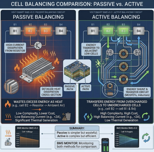
Passive balancing is the most common and cost-effective method. It works by using a small resistor to “bleed off” excess energy as heat from any cell that reaches its maximum charge voltage before the others. This allows the lower-voltage cells to continue charging and “catch up.”
The primary limitation is that it only functions at the very top of the charge cycle, typically above 3.4V per cell. Furthermore, the balancing current is very low, usually between 30mA and 200mA, making it a slow process that is best suited for maintaining balance in a pack built with new, high-quality, closely matched cells. This type of balancing is a foundational element in a good 24V solar system wiring diagram.
Active Balancing Explained
Active balancing is a more advanced and efficient technology. Instead of wasting energy as heat, an active balancer uses capacitors or inductors to actively shuttle energy from the highest voltage cell(s) to the lowest voltage cell(s). This process can occur across the entire state of charge range, not just at the top.
With significantly higher balancing currents (0.5A to over 2A), active balancers can correct large voltage deviations much faster. This makes them the superior choice for large battery banks, packs built from used or salvaged cells, or any application where maximizing usable capacity and cycle life is the absolute priority. The powerful balancing of a JK BMS is why many consider it the best smart BMS for custom LiFePO4 battery builds in demanding situations.
This decision matrix can help you determine the most suitable balancing technology for your build.
| Factor | Choose Passive Balancing If… | Choose Active Balancing If… |
|---|---|---|
| Cell Quality | Using new, Grade A, closely matched cells from a reputable supplier. | Using used, salvaged, or B-grade cells with known capacity variations. |
| Pack Capacity | Your pack is relatively small (e.g., under 200Ah). | Your pack is large (e.g., 280Ah, 400Ah, or larger). |
| Budget | Cost is a primary constraint. Passive BMS units are more affordable. | Maximizing performance and longevity is worth the higher upfront cost. |
| Use Case | The battery will be regularly fully charged, allowing for top balancing. | The battery will operate in a partial state of charge (PSOC) for extended periods. |
| Parasitic Drain | You need the absolute lowest idle power consumption. | A slightly higher parasitic drain (to power the balancer) is acceptable. |
Installation & Configuration: Integrating the Best Smart BMS for Custom LiFePO4 Battery Builds
Proper installation and configuration are just as critical as selecting the right hardware. A wiring mistake or incorrect parameter can render the BMS ineffective, exposing your expensive cells to danger. Follow a methodical approach, double-check every connection, and adhere to all electrical safety standards.
Before you begin, ensure you have all necessary safety equipment, including safety glasses and insulated gloves. Working with high-current DC systems is inherently hazardous.
Wiring Procedure
The wiring sequence is critical to avoid damaging the BMS. Always connect the components in the correct order.
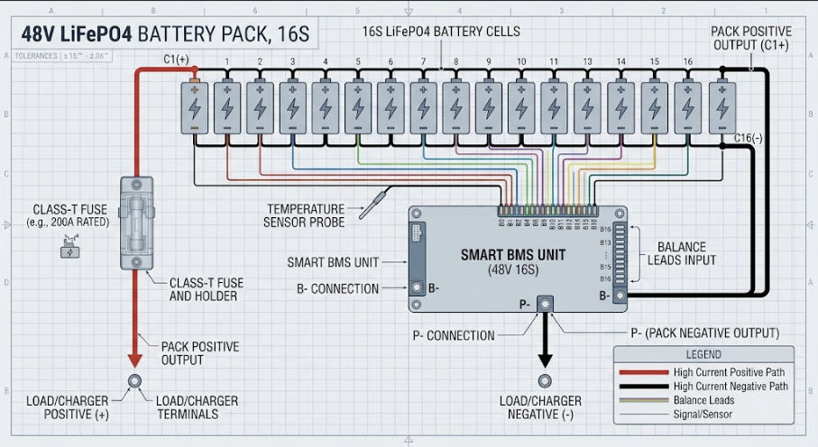
- Connect Balance Leads: Start by connecting the balance harness to each cell group, beginning with the main negative cell (B0 or B-) and proceeding sequentially to the main positive cell (e.g., B1, B2…B16). Ensure the harness is disconnected from the BMS during this step.
- Connect Main Negative (B-): Connect the main negative terminal of the battery pack to the “B-” pad or terminal on the BMS using appropriately sized cable.
- Connect Load/Charger Negative (P- or C-): For a common port BMS, connect the “P-” (or sometimes labeled C-) terminal to your main negative solar bus bar, which goes to your inverter and charge controller.
- Plug in Balance Harness: Once all other wires are secure, plug the balance lead connector into the BMS. This is the final step to activate the BMS.
Always use a high-quality Class T fuse on the positive line between your battery and the system bus bar for catastrophic overcurrent protection. This is a requirement under the National Electrical Code (NEC) for battery systems, as outlined in Article 480.
Initial Software Configuration
Once wired, connect to your BMS via the Bluetooth app. The first step is to enter the parameter settings and configure the protection thresholds to match your specific LiFePO4 cells. These values are found on your cell’s datasheet.
Key parameters to set immediately include:
- Cell Overvoltage Protection (HVC): Typically 3.65V. The BMS will disconnect charging if any cell exceeds this.
- Cell Undervoltage Protection (LVC): Typically 2.5V. The BMS will disconnect the load if any cell drops below this.
- Pack Capacity: Enter your battery pack’s total capacity in Amp-hours (e.g., 280Ah).
- Temperature Cutoffs: Set “Charge Low Temp” to 2°C or 3°C to be safe. Set “Charge High Temp” to ~45°C and “Discharge High Temp” to ~60°C.
- Current Limits: Configure overcurrent protection values based on your BMS rating and system wiring.
After setting the parameters, perform a full charge cycle to allow the BMS to perform its first top balance. Monitor the cell voltages in the app to ensure they are converging. Proper setup is crucial for any off-grid system, from a solar setup for a micro cabin to a large-scale residential installation.
Frequently Asked Questions
What is the difference between a common port and a separate port BMS?
A common port BMS uses a single terminal (often labeled P- or C-) for both charging and discharging negative connections, which is ideal for most solar applications where an inverter/charger is used. A separate port BMS has two distinct terminals: a C- for the charger negative and a P- for the load (inverter) negative, which can complicate wiring and is less common. For nearly all DIY solar projects, a common port model is the best smart BMS for custom LiFePO4 battery builds.
How critical is the low-temperature charging protection feature?
Low-temperature charging protection is arguably the single most important safety feature for any LiFePO4 battery used in a climate that experiences freezing temperatures. Charging below 0°C (32°F) causes irreversible lithium plating, which permanently reduces capacity and can create internal short circuits, posing a severe fire risk. Therefore, this programmable cutoff is a non-negotiable requirement when selecting the best smart BMS for custom LiFePO4 battery builds.
Can I use two separate BMS units on battery banks connected in series?
No, you absolutely cannot connect two battery packs with their own BMS units in series to create a higher voltage system (e.g., connecting two 24V packs to make 48V). The BMS units are not designed to handle the higher system voltage across their circuitry and will be destroyed. To build a higher voltage battery, you must connect all cells in series and use a single, appropriately rated BMS, such as a 16S (48V) model, which is the correct approach for the best smart BMS for custom LiFePO4 battery builds.
What does “parasitic drain” mean for a smart BMS?
Parasitic drain is the small amount of power the BMS itself consumes from the battery to power its own electronics, including the microcontroller, Bluetooth module, and balancing circuits, even when the battery is not in use. While typically very low (in the microamp or low milliamp range), this continuous drain can slowly discharge a battery over many months of storage. When considering the best smart BMS for custom LiFePO4 battery builds, models with active balancers tend to have a slightly higher parasitic drain than those with passive balancers.
How do I properly wire the balance leads to the cells?
The balance leads must be connected in the correct sequence to prevent damage to the BMS. Always start with the first black wire (B0) connected to the main negative terminal of the entire battery pack. Then, connect the subsequent wires (B1, B2, B3, etc.) to the positive terminal of each corresponding cell group in series order. The final red wire should land on the main positive terminal of the pack. Only after verifying the correct voltage progression with a multimeter should you plug the harness into the best smart BMS for custom LiFePO4 battery builds.
Is a higher balancing current always better in a smart BMS?
A higher balancing current is generally better, as it allows the BMS to correct cell imbalances more quickly and effectively. A low current (e.g., 30mA) might struggle to keep up with drift in a large capacity pack, while a high current (e.g., 1-2A from an active balancer) can correct significant deviations rapidly. For large packs or those using used cells, a higher balancing current is a key feature to look for in the best smart BMS for custom LiFePO4 battery builds.
What is the purpose of the CAN bus or RS485 communication ports?
CAN bus and RS485 are robust communication protocols that allow the BMS to establish a “closed-loop” connection with compatible solar inverters or system controllers, like those from Victron or Sol-Ark. This enables the BMS to share detailed battery data (SOC, voltage, current limits, temperature) directly with the inverter, allowing the inverter to make more intelligent charging and discharging decisions. This integration is a hallmark of the best smart BMS for custom LiFePO4 battery builds used in advanced systems.
How do I reset a BMS that has tripped on a fault?
Most smart BMS units will automatically reset once the fault condition is cleared (e.g., the load is removed after an overcurrent trip, or a charger is connected after an undervoltage trip). Some faults, particularly undervoltage, may require connecting a charger to “wake up” the BMS. The mobile app for the best smart BMS for custom LiFePO4 battery builds often includes a “Clear Faults” or reset button that can manually clear alarms after the underlying issue has been resolved.
Can I parallel multiple DIY battery packs, each with its own smart BMS?
Yes, you can connect multiple identical battery packs in parallel, where each pack has its own dedicated BMS. To do this safely, ensure all packs are at the same voltage before connecting them to a common bus bar. Each pack should have its own overcurrent protection (fuse or breaker). This modular approach is a common and effective way to scale up capacity using the best smart BMS for custom LiFePO4 battery builds for each sub-pack.
What are MOSFETs and why are they important in a BMS?
MOSFETs (Metal-Oxide-Semiconductor Field-Effect Transistors) are powerful semiconductor switches that the BMS uses to control the flow of current into and out of the battery pack. A bank of high-quality, low-resistance MOSFETs allows the BMS to handle high currents with minimal heat generation and to disconnect the battery almost instantaneously during a fault condition. The quality and quantity of MOSFETs are a key indicator of the power-handling capability of the best smart BMS for custom LiFePO4 battery builds.
Does a smart BMS calculate State of Charge (SOC) accurately?
A smart BMS calculates SOC using a method called coulomb counting, which tracks the amp-hours flowing in and out of the battery. While generally accurate, this can drift over time. To maintain accuracy, the SOC needs to be periodically recalibrated by fully charging the battery, which allows the BMS to reset its counter to 100% when the charge current tapers off at the correct voltage. This calibration process is an important maintenance step for the best smart BMS for custom LiFePO4 battery builds.
Should I enable the pre-charge function on my smart BMS?
Yes, if your BMS offers a pre-charge function, you should absolutely enable it, especially when connecting to a large inverter with significant input capacitance. The pre-charge circuit uses a resistor to slowly charge the inverter’s capacitors before the main contactor or MOSFETs close. This prevents a massive inrush of current that can arc and damage the BMS switches or trip overcurrent protection. This feature is a strong indicator of a high-quality and best smart BMS for custom LiFePO4 battery builds.
What role does the temperature sensor play in the best smart BMS for custom LiFePO4 battery builds?
The temperature sensor is a critical safety and longevity component. The BMS uses its readings to enforce thermal protection limits, most importantly preventing charging below freezing temperatures. It also protects against overheating during heavy charge or discharge cycles by disconnecting the circuit if temperatures exceed safe limits. A quality installation of the best smart BMS for custom LiFePO4 battery builds often involves placing multiple sensors to monitor different areas of the battery pack for comprehensive thermal data.
Why does the charge current rating sometimes differ from the discharge rating on a BMS?
On some budget-oriented BMS models, like many from Daly, the charge current rating is set to half of the discharge current rating. This is a design choice to save cost by using fewer MOSFETs on the charging circuit, as charging is often done at a lower, more controlled rate than peak discharging. However, this can be a significant limitation in solar applications with large arrays. The best smart BMS for custom LiFePO4 battery builds, such as those from JBD and JK, typically feature symmetrical ratings where the charge and discharge currents are equal.